
Even with a perfectly leveled build plate and properly tensioned belts, many 3D prints still suffer from frustrating visual defects: bulging outer corners, rough top surfaces with excess plastic, gaps between perimeter walls, or inconsistent extrusion immediately following rapid speed changes.
The good news is that these artifacts are rarely caused by hardware faults. In most cases, they stem from two uncalibrated slicer parameters: Flow Rate and Pressure Advance.
In this step-by-step guide, you will learn how to use the built-in calibration suite inside OrcaSlicer to dial in both settings with surgical precision, resulting in crisp 90-degree corners, accurate dimensional tolerances, and smooth top layers.
📌 Key Takeaways
- Proper Calibration Order: Why you must always calibrate Flow Rate before tuning Pressure Advance.
- Two-Stage Flow Test (Pass 1 & Pass 2): How to read surface test chips to eliminate over-extrusion and under-extrusion.
- Pressure Advance (Pattern & Tower Methods): How to compensate for internal nozzle pressure during high-speed direction changes.
- Per-Filament Profiles: Saving custom values individually for PLA, PETG, and ABS workflows.
1. Why Calibrate Flow Rate and Pressure Advance Together?
Before running test prints, it helps to understand how these two parameters interact:
- Flow Ratio: Controls the exact volume of plastic pushed by the extruder to account for slight filament diameter tolerances and polymer thermal expansion. If your flow ratio is too high, excess plastic will mask the true corner behavior during Pressure Advance testing.
- Pressure Advance (PA): Anticipates toolhead acceleration and deceleration. When the printhead slows down for a sharp 90-degree turn, residual pressure inside the melt zone continues oozing filament, causing rounded “bulging corners.” PA reduces extrusion slightly before deceleration and restores it upon acceleration.
Golden Rule: Always calibrate Flow Rate first, followed immediately by Pressure Advance.
2. Step 1: Calibrating Flow Rate in OrcaSlicer
OrcaSlicer includes a native calibration generator based on top-surface inspection chips (Pass 1 and Pass 2).
Stage A: Pass 1 (Coarse Adjustment)
- Open OrcaSlicer and select your printer profile (e.g., Bambu Lab A1 Mini, Creality Ender-3 V3 KE, or Anycubic Kobra 2 Pro) along with your target filament.
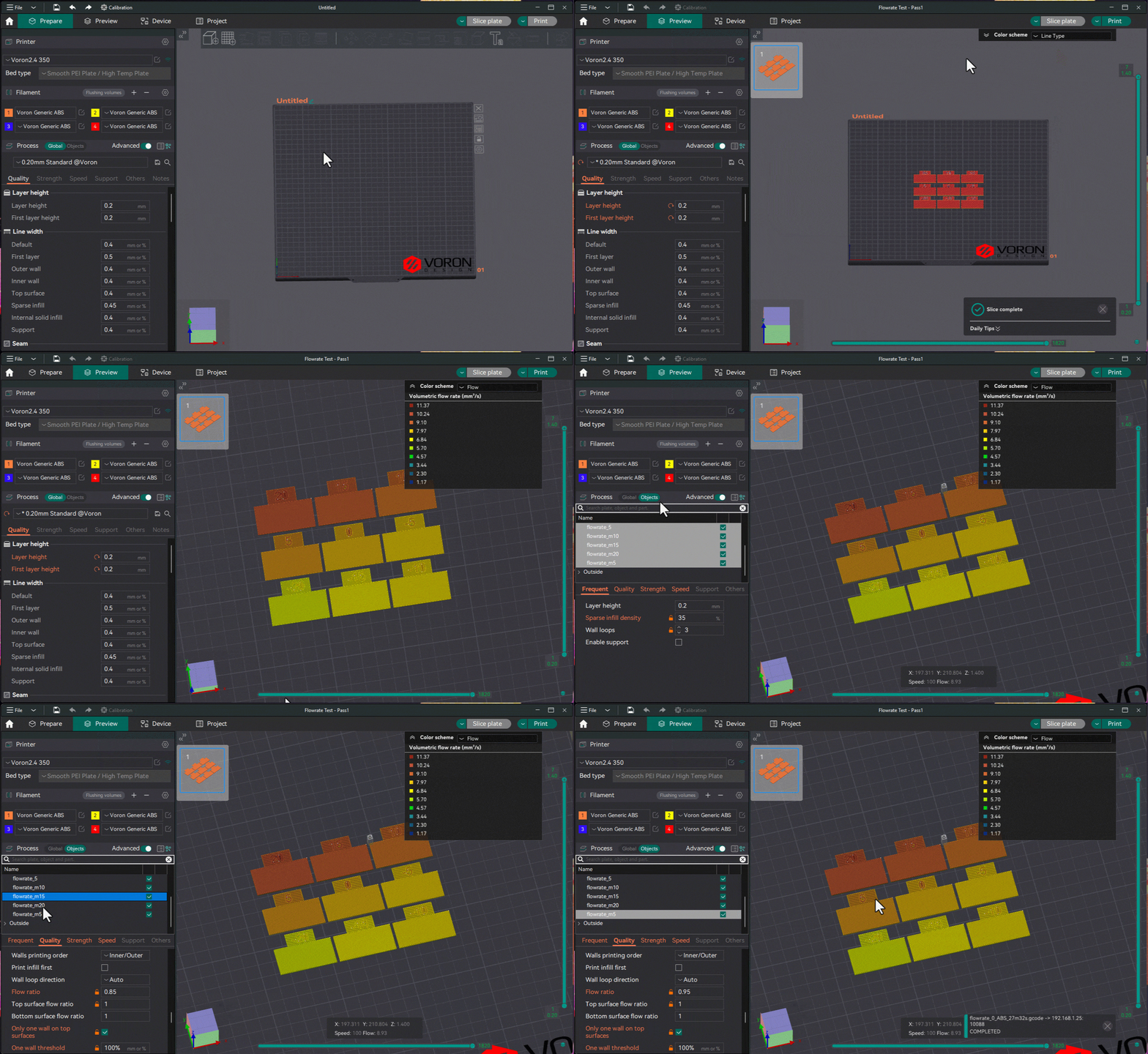
- In the top-left menu bar, navigate to Calibration > Flow Rate > Pass 1.
- The slicer automatically generates 9 numbered swatches ranging from
-20to+20(representing percentage adjustments). - Slice and print the plate at your filament’s standard printing temperature (for instance, 210 °C for PLA or 240 °C for PETG).
How to evaluate Pass 1:
Inspect the top surface of each chip under good lighting and feel the texture with your fingertip. Identify the chip with the smoothest finish—free from gaps between extrusion lines (under-extrusion) and free from rough ridges along the edges (over-extrusion).
- Formula:
New Flow = Current Flow × (100 + Best Chip Value) / 100. - Example: If your current Flow Ratio is
0.98and chip-5looks cleanest, calculate0.98 × 0.95 = 0.931. - Enter this updated figure into the Flow ratio field inside your filament settings and save.
Stage B: Pass 2 (Fine Tuning)
- With the updated Flow Ratio saved, go back to Calibration > Flow Rate > Pass 2.
- OrcaSlicer generates 10 new chips ranging from
-9to0for fine refinement. - Print and inspect the surface finish again. Apply the same formula using your Pass 1 result and save the final number to your filament profile.
3. Step 2: Calibrating Pressure Advance (PA)
Once volumetric flow is accurate, you can dial in crisp corners and clean seams.
- Start a clean project in OrcaSlicer.
- Open the top menu and select Calibration > Pressure Advance.
- Choose your extruder architecture:
- Direct Drive (DDE): For printheads with the extruder motor mounted directly above the hotend. Typical values range between
0.015and0.045. - Bowden: For setups using a long PTFE tube between the extruder and hotend. Typical values range between
0.200and0.600.
- Direct Drive (DDE): For printheads with the extruder motor mounted directly above the hotend. Typical values range between
- Choose PA Pattern (chevron lines) or PA Tower. The PA Pattern method prints faster and uses minimal filament.
How to evaluate the result:
- On the PA Pattern, examine the sharp apexes (corners) of each printed chevron from bottom to top.
- Values that are too low produce bulging, rounded corners with excess material.
- Values that are too high cause thinning or gaps right at the sharp tip of the corner.
- Select the line number where the corner forms a sharp, clean, continuous 90-degree angle.
Saving the Value in OrcaSlicer
- Click the edit icon next to your active filament profile.
- Under the Filament tab, check Enable pressure advance.
- Enter your measured value (e.g.,
0.024) into the Pressure advance field. - Click the save icon to lock the setting into your profile.
4. Quick Reference Table by Filament Type
| Material | Typical Nozzle Temp | Common Flow Ratio Range | Typical PA Range (Direct Drive) |
|---|---|---|---|
| PLA / PLA+ | 205 °C – 215 °C | 0.95 – 1.00 | 0.018 – 0.035 |
| PETG | 235 °C – 245 °C | 0.92 – 0.97 | 0.030 – 0.055 |
| ABS / ASA | 250 °C – 265 °C | 0.90 – 0.95 | 0.020 – 0.040 |
| TPU (95A) | 220 °C – 230 °C | 1.00 – 1.05 | 0.060 – 0.120 |
Final Verdict
Spending 30 minutes calibrating Flow Rate and Pressure Advance for each filament brand and polymer type dramatically improves print quality. Mechanical assemblies snap together without manual filing, embossed text appears sharp, and you can push higher print speeds without sacrificing dimensional accuracy.